RAKKA 60 DIY Kit Guide
Disclaimer
The contents of the package content, including plate, screws, etc. described in these instructions are limited to the RAKKA 60 DIY Kit sold directly by us, and some of the contents may be different if you purchased them from a source other than us.
Disclaimer
Our 0.1mm is real and usable: with the key travels all set to 0.1mm, a steady press (excluding problems of the stability of the switch and the human finger) should not cause any problems.
This has been widely tested by our first users in China (> 700 users).
If not assembled correctly, it will lead to inaccurate distance detection and even problems such as disrupted press and false press.
Installation
Check that the package contents are complete
- 1x PCB
- 1x Plate
- 1x Foam (1x space foam, 6x single key foam)
- 1x USB cable
- 1x Daughterboard
- 1x SH 1.0 4P cable (for Daughterboard)
- 8x Black nylon M2 screws
- 70x Gateron KS-20 White switches
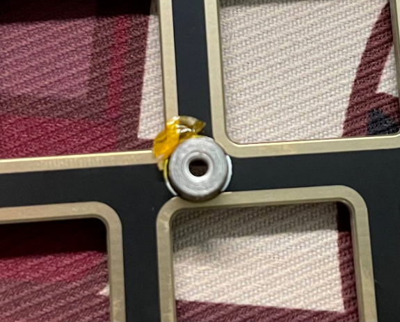
Remove the yellow tape from the nut post on the plate.
Mounting the switch
Since the Gateron KS-20 White switch is a little bit bigger compared to normal mechanical switches (it also has snaps on the left and right), it is a little bit more difficult to mount. We recommend installing the switch to the plate first.
Since there is no full keyboard RGB, there is no need to agonize over whether to mount it forward or backward. Only the CapsLock position needs to be noted with the light position underneath.
When installing the switch, you need to use some skills, don't use your thumb to press down directly, it will hurt (x_x).
Install stabilizers
The steps of installing PCB-mount stabilizers and plate-mount stabilizers are different, there are many tutorials on the Internet for reference.
Install foams
- Place the foam from the opposite side of the plate
- Put on the space foam
Combine the plate and the PCB
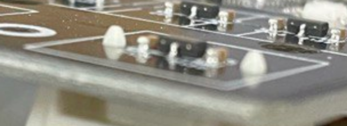
To ensure the accuracy of the distance detection, after the combination, lightly press on the reverse side of the PCB at each switch position to make sure that the feet of the switch have been fully inserted into the holes of the PCB.
Every switch should be look like this!
When finished, screw in the 8 screws. Nylon screws are provided, which have a certain degree of elasticity, while the PCB and the plate have a certain degree of elasticity, together with the elasticity of the nylon screws can achieve a more stable fixing effect.
However, screwing nylon screws is not the same as screwing ordinary screws, and should not be screwed that tighten. Be sure to press the switch firmly before screwing. Use your fingers to press the corresponding holes on the front of the plate, and stop screwing once your fingers feel that a screw is coming out.
Check if it is working properly
Caution
- Do not touch the switches while plugged in the USB cable, otherwise the auto-calibration process will be affected, resulting in errors in the detected travel
- Do not allow objects with strong magnetism to come close to the keyboard (including, but not limited to, iPhone, Apple Watch), which can cause errors in the detected travel
Open kb.rakka.cn (CN) or kb.rakka.dev (outside mainland China), connect to the keyboard, switch to the debugging tab, and press each key individually to see if the distance detection is normal. For Gateron KS-20 White which has 4.1 total travel, pressing to the end should be 4.10mm (or close to 4.10mm, taking into account that there is a tolerance for magnetizing the magnets in the switch).
Readings below 4.0 definitely should be considered a possible installation error.
Installation of keycaps, installation into the case